
 CN
 EN

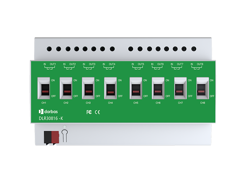
8-channel 16A switch actuator module
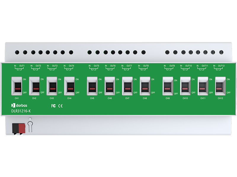
DLR30816-K
The emergency cut-off switch actuator is a modular mounting device with 8 outputs. It connects to the EIB/KNX system via EIB bus terminals. Engineering design tool ETS (version ETS4.0 or higher) is used for physical address assignment and parameter configuration.
Each output of the emergency cut-off switch actuator supports a maximum load current of 16A. It integrates 8 smart relays. Each channel can independently control 3300W lighting switching. The relay is equipped with a manual emergency cut-off dial and features magnetic latching function. The 8-channel emergency cut-off switch actuator comes with 4 I/O dry contact input interfaces, which can receive control commands for switches, curtains, dimming, scenes and more.
- Independently controls 8 channels of lights/loads;
- Equipped with manual emergency cut-off dial; relays feature magnetic latching function;
- Delay on/off, timed switching and cyclic switching functions;
- On-site status saving and restoration, status query and response, and selection of relay switching status upon bus power failure and voltage recovery;
- Scene combination control function;
- 4-channel I/O input for receiving control commands of switches, curtains, dimming, scenes, etc.;
- Supports direct linkage with fire emergency lighting;
- I/O wiring communication distance: less than 10m
- Main Output: 8-channel design, 250V AC (50/60Hz) 16A per channel
- Bus Input: 21-30VDC
- Bus Current: ≤20mA
- Operating Power: ≤0.6W
- Output (per channel): Resistive load: max 16A
- Housing Material: PA66
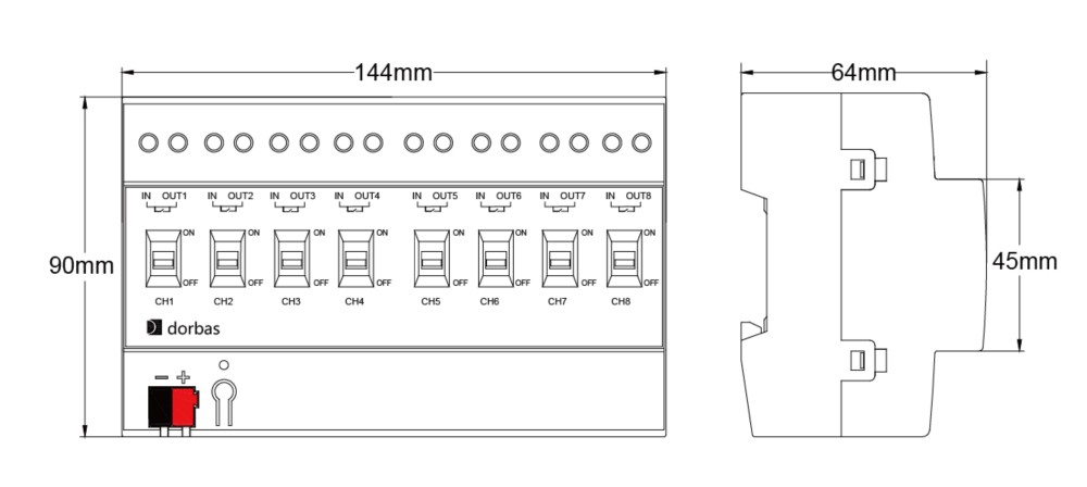
- Dimensions (HxWxD): 144mm x 90mm x 64mm
- Weight (approx): 0.38KG
- Mounting: 35mm DIN rail mounting
- Pollution Degree (IEC60664-1): 2
- Ingress Protection (IEC60529): IP20
- Protection Class (IEC61140): III
- Overvoltage Category (IEC60664-1): III
- Operating Temperature: 5°C - 45°C
- Storage Temperature: -25°C ... +55°C
- Transport Temperature: -25°C ... +70°C
- Relative Humidity: Max 90%
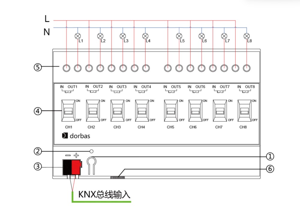
Installation Instructions
This device is installed in the distribution box and can be mounted on 35 mm DIN rails complying with DIN EN 60715 standard. To facilitate quick installation of the device inside the distribution box, proper operation, testing, inspection and maintenance of the device must be ensured.
Safe Operation and Maintenance
(1) Maintain a well-ventilated environment.
(2) Keep away from moisture, vibration and dust during operation.
(3) Do not expose to rain, liquids or corrosive gas.
(4) Dry the device promptly if it gets wet or contaminated by liquid.
(5) Contact professional maintenance personnel or our company if the device malfunctions.